- WARNING
This product has been developed by Aceinna exclusively for commercial applications. It has not been tested for, and Aceinna makes no representation or warranty as to conformance with, any military specifications or that the product is appropriate for any military application or end-use. Additionally, any use of this product for nuclear, chemical, biological weapons, or weapons research, or for any use in missiles, rockets, and/or UAV’s of 300km or greater range, or any other activity prohibited by the Export Administration Regulations, is expressly prohibited without the written consent of Aceinna and without obtaining appropriate US export license(s) when required by law. Diversion contrary to law is prohibited.
©2018 Aceinna, Inc. All rights reserved. Information in this document is subject to change without notice.
**Table of Contents **
1.2 Overview of the MTLT Series Inertial Systems 2
2.2 Power Input and Power Input Ground 3
3 Installation and Operation of NAV-VIEW 4
3.1 NAV-VIEW Computer Requirements 4
3.12 Read Unit Configuration 13
4.1 MTLT Series Default Coordinate System 15
4.2 Dynamic MTLT Theory of Operation 16
4.2.1 MTLT1xxD Advanced Settings 17
4.2.2 MTLT1xxD Built-In Test 18
4.3 Tilt Alarm (Independent vs. Cone Angle) 19
5.2 Equipment Leveling and lockout 20
5.3 Aerial Work Platform Safety 21
7 Communicating with the MTLT1 Series 26
7.2.2 Algorithm Reset Command 27
7.2.3 Algorithm Reset Response 27
7.3 Output Packets (Polled) 27
7.3.1 Identification Data Packet 27
7.3.3 Test 0 (Detailed BIT and Status) Packet 28
7.4 Output Packets (Polled or Continuous) 29
7.4.1 Angle Data Packet 6 (Default Data) 29
8.2 Continuous Packet Type Field 32
8.3 Digital Filter Settings 32
8.7 Commands to Program Configuration 35
9.1 Built In Test (BIT) and Status Fields 39
9.2 Master BIT and Status (BITstatus) Field 41
9.5 hardwareEnvironmentalBIT Field 42
9.9 softwareAlgorithmBIT Field 44
9.15 Configuring the Master Status 45
9.15.1 hardwareStatusEnable Field 45
9.15.2 comStatusEnable Field 46
9.15.3 softwareStatusEnable Field 46
9.15.4 sensorStatusEnable Field 46
10 Appendix A. Mechanical Specifications 47
11 Appendix C. Sample Packet-Parser Code 48
12 Appendix D. Sample Packet Decoding 55
13 Warranty and Support Information 57
13.3.2 Identification and Protection 57
13.3.3 Sealing the Container 58
13.3.5 Return Shipping Address 58
** About this Manual**
The following annotations have been used to provide additional information.
NOTE
Note provides additional information about the topic.
EXAMPLE
Examples are given throughout the manual to help the reader understand the terminology.
IMPORTANT
This symbol defines items that have significant meaning to the user
 WARNING
The user should pay particular attention to this symbol. It means there is a chance that physical harm could happen to either the person or the equipment.
Introduction
Manual Overview
This manual provides a comprehensive introduction to Aceinna’s MTLT Series industrial tilt sensor products. For users wishing to get started quickly, please refer to the three page quick start guide included with each shipment. Table 1 table highlights the content in each section and suggests how to use this manual.
- Manual Content
| Manual Section | Who Should Read ? |
|---|---|
Section 1:
Manual Overview
|
All customers should read
sections 1.1 and 1.2.
|
**Section 2: **
Connections
|
Customers who are connecting the
MTLT Series products into a
system with their own power
supply and cable.
|
**Section 3: **
Installation and Operation of
NAV-VIEW
|
Customers who are installing the
MTLT Series products into a
system and need details on using
NAV-VIEW.
|
**Section 4: **
Theory of Operation
|
All customers should read Section
4.
As the MTLT Series products are
inter-related, use the chart at
the beginning of Section 4 to
ensure that you get an overview
of all of the functions and
features of your MTLT Series
system.
|
**Section 5: **
Application Guide
|
Customers who want product
configuration tips for operating
the MTLT Series tilt sensors in a
wide range of applications.
|
**Section 6-9: **
Programming, Communicating,
Advanced Commands and BIT
|
Customers who wish to communicate
with the MTLT Series system for
sensor data, should review
Section 6 and 7. Section 8 is for
users who wish to configure the
MTLT Series operating parameters
(e.g., baud rate or power-up
output rate) without NAV-VIEW.
|
Overview of the MTLT Series Inertial Systems
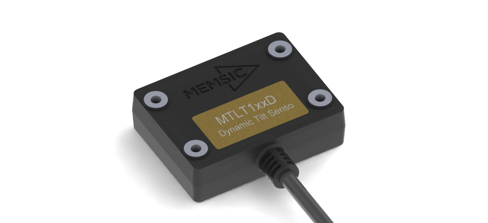
This manual provides a comprehensive introduction to the use of Aceinna’s MTLT Industrial Tilt Sensor products listed in Table 2. This manual is intended to be used as a detailed technical reference and operating guide for the MTLT Series. Aceinna’s MTLT Series products combine the latest in high-performance commercial MEMS (Micro-electromechanical Systems) sensors and digital signal processing techniques to provide a small, cost-effective alternative to existing tilt sensors.
- MTLT Series Feature Description
| Series | Product | Features |
|---|---|---|
| MTLT1 Series | MTLT110S | Accelerometer based
static tilt sensor.
3-DOF Accelerometer
data plus static Roll
and Pitch, plus a
single pin tilt
alarm. Plastic IP67
Housing with a 1.0
degree
over-temperature
accuracy on static
tilt angles.
|
| MTLT105S | Accelerometer based
static tilt sensor.
3-DOF Accelerometer
data plus static Roll
and Pitch, plus a
single pin tilt
alarm. Plastic IP67
Housing with a 0.5
degree
over-temperature
accuracy on static
tilt angles.
|
|
| MTLT101S | Accelerometer based
static tilt sensor.
3-DOF Accelerometer
data plus static Roll
and Pitch, plus a
single pin tilt
alarm. Plastic IP67
Housing with a 0.1
degree
over-temperature
accuracy on static
tilt angles.
|
|
| MTLT105D | Gyro compensated
dynamic tilt sensor.
3-DOF Accelerometer
data, 3-DOF Gyro
data, plus dynamic
Roll and Pitch, plus
a single pin tilt
alarm. Plastic IP67
Housing with a 0.5
degree
over-temperature
accuracy on static
tilt angles and 2.0
degree accuracy on
dynamic tilt angles.
|
|
| MTLT101D | Gyro compensated
dynamic tilt sensor.
3-DOF Accelerometer
data, 3-DOF Gyro
data, plus dynamic
Roll and Pitch, plus
a single pin tilt
alarm. Plastic IP67
Housing with a 0.1
degree
over-temperature
accuracy on static
tilt angles and 1.0
degree accuracy on
dynamic tilt angles.
|
The MTLT Series continues in Aceinna’s long history of inertial sensors. We have 20 years of history building inertial and tilt sensor products. The MTLT Series comes in both a static (accelerometer only) configuration for stationary or low speed applications, and a dynamic (gyro compensated) configuration for mobile applications. Both static and dynamic configurations use the same high-performance microprocessor for on-board angle computations, and high-accuracy accelerometers.
The MTLT1 series sensors are housed in a sealed IP67 plastic enclosure ideal for outdoor or external applications. The MTLT1 uses a standard RS232 communication protocol for easy integration and a wide 9 – 32 volt input power range.
In addition to the accelerometers, the dynamic MTLT also includes a 3-axis gyro for dynamic compensation. Traditional accelerometer only tilt sensors are great in static or slow moving applications where the linear accelerations are insignificant compared to the Earth’s gravity vector. However, when placed in a moving vehicle (land, water, or aerial), the linear accelerations of the vehicle motion can be interpreted as changes in tilt. With a gyro compensated tilt sensor, these linear accelerations can be filtered out by the on-board Kalman filter resulting in an accurate tilt measurement across all dynamic.
Each sensor in the MTLT family includes a tilt alarm. The tilt alarm is a single pin output that is raised high when the tilt exceeds a user defined threshold. The user defined threshold can be set using the RS232 port. The tilt alarm is ideal for low-cost applications that may not include a microprocessor for reading the tilt angles. After the threshold is set, the alarm pin can be attached directly to a control relay to lock out equipment when dangerous tilt levels are exceeded, or simply attached to an LED to give an operator an indication that he/she is driving on an unsafe incline.
The MTLT Series is supported by Aceinna’s NAV-VIEW, a powerful PC-based operating tool that provides complete field configuration, diagnostics, charting of sensor performance, and data logging with playback.
Connections
Connections
The MTLT1 Series has 6 flying leads on a 1 meter long cable
- Connector Pin Assignments
| Color | Signal |
| Red | Power Input |
| Black | Power Return |
| Green | RS232-RX |
| Yellow | Tilt Alarm |
| Orange | RS232-TX |
| Brown | RS232 Return |
The maintain IP67 performance, the user must carefully seal the terminations of the flying leads.
Power Input and Power Input Ground
Power is applied to the MTLT1 Series sensor on red and black leads. The black wire is ground; the red wire should have 9 to 32 VDC.
- WARNING
Do not reverse the power leads or damage may occur.
Serial Data Interface
The serial interface is standard RS-232, 9600, 19200, 38400, or 57600 baud, 8 data bits, 1 start bit, 1 stop bit, no parity, and no flow control and will output at a user configurable output rate. The green and orange leads are designated as the main RS-232 interface pins. The serial data settings can be configured on a MTLT1 Series unit with NAV-VIEW. In order to set the serial data interface, select Unit Configuration, under the Menu Tab.
Alarm
The Alarm output is normally pulled low by a current sinking transistor. When the Alarm threshold is exceeded the transistor is turned off and the output will be pulled high by a 10K 1/16W resistor to the internal 3.3 Volt power supply.
Installation and Operation of NAV-VIEW
NAV-VIEW allows users to control all aspects of the MTLT Series operation including data recording, definable alarm threshold and data transfer. In addition you will be able to control the orientation of the unit, sampling rate, packet type, and filter settings.
Connections
The MTLT1 Series Inertial Systems products are shipped flying leads. To connect to NAV-VIEW the flying leads can be attached to a standard DB9 connector.
- Connect the green lead (RS232-RX) to pin 3 of the DB9 connector
- Connect the orange lead (RS232-TX) to pin 2 of the DB9 connector
- Connect the brown lead (RS232-GND) to pin 5 of the DB9 connector
- Connect the red lead (+) to power supply positive, 9-32VDC
- Connect the black lead (-) to power supply negative
- Connect the yellow lead (Alarm) to oscilloscope or DMM. GND is brown lead
Note: Allow at least 60 seconds after power up for the MTLT1 Series product to
initialize. The MTLT1 Series needs to be held motionless during this period.
WARNING
Do not reverse the power leads! Reversing the power leads to the MTLT Series can damage the unit; although there is reverse power protection, Aceinna is not responsible for resulting damage to the unit should the reverse voltage protection electronics fail.
Setting up NAV-VIEW
With the MTLT Series product powered up and connected to your PC serial port, open the NAV-VIEW software application.
1. NAV-VIEW should automatically detect the MTLT Series product and display the serial number and firmware version if it is connected.
2. If NAV-VIEW does not connect, check that you have the correct COM port selected. You will find this under the “Setup” menu. Select the appropriate COM port and allow the unit to automatically match the baud rate by leaving the “Auto: match baud rate” selection marked.
3. If the status indicator at the bottom is green and states,
 , you’re ready to go. If the status indicator doesn’t say
connected and is red, check the connections between the MTLT Series
product and the computer, check the power supply, and verify that the
COM port is not occupied by another device.
, you’re ready to go. If the status indicator doesn’t say
connected and is red, check the connections between the MTLT Series
product and the computer, check the power supply, and verify that the
COM port is not occupied by another device.
4. Under the “View” menu you have several choices of data presentation. Graph display is the default setting and will provide a real time graph of all the MTLT Series data. The remaining choices will be discussed in the following pages.
Data Recording
NAV-VIEW allows the user to log data to a text file (.txt) using the simple interface at the top of the screen. Customers can now tailor the type of data, rate of logging and can even establish predetermined recording lengths.
To begin logging data follow the steps below (See Figure 1):
- Locate the
 icon at the top of the page or select “Log to
File” from the “File” drop down menu.
icon at the top of the page or select “Log to
File” from the “File” drop down menu. - The following menu will appear.
- Log to File Dialog Screen
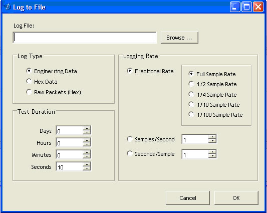
- Select the “Browse” box to enter the file name and location that you wish to save your data to.
- Select the type of data you wish to record. “Engineering Data” records the converted values provided from the system in engineering units, “Hex Data” provides the raw hex values separated into columns displaying the value, and the “Raw Packets” will simply record the raw hex strings as they are sent from the unit.
- Users can also select a predetermined “Test Duration” from the menu. Using the arrows, simply select the duration of your data recording.
- Logging Rate can also be adjusted using the features on the right side of the menu.
- Once you have completed the customization of your data recording, you
will be returned to the main screen where you can start the recording
process using the
 button at the top of the page or
select “Start Logging” from the “File” menu. Stopping the data
recording can be accomplished using the
button at the top of the page or
select “Start Logging” from the “File” menu. Stopping the data
recording can be accomplished using the  button and the
recording can also be paused using the
button and the
recording can also be paused using the  button.
Data Playback
In addition to data recording, NAV-VIEW allows the user to replay saved data that has been stored in a log file.
- To playback data, select “Playback Mode” from the “Data Source” drop
down menu at the top.

- Selecting Playback mode will open a text prompt which will allow users to specify the location of the file they wish to play back. All three file formats are supported (Engineering, Hex, and Raw) for playback. In addition, each time recording is stopped/started a new section is created. These sections can be individually played back by using the drop down menu and associated VCR controls.
- Once the file is selected, users can utilize the VCR style controls at the top of the page to start, stop, and pause the playback of the data.
- NAV-VIEW also provides users with the ability to alter the start time
for data playback. Using the
 slide bar at the top of the
page users can adjust the starting time.
slide bar at the top of the
page users can adjust the starting time.
Raw Data Console
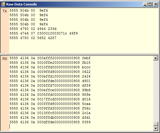
NAV-VIEW offers some unique debugging tools that may assist programmers in the development process. One such tool is the Raw Data Console. From the “View” drop down menu, simply select the “Raw Data Console”. This console provides users with a simple display of the packets that have been transmitted to the unit (Tx) and the messages received (Rx). An example is provided in Figure 2.
- Raw Data Console
Packet Statistics View
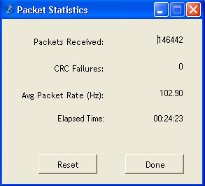
Packet statistics can be obtained from the “View” menu by selecting the “Packet Statistics” option (See Figure 3). This view simply provides the user with a short list of vital statistics (including Packet Rate, CRC Failures, and overall Elapsed Time) that are calculated over a one second window. This tool should be used to gather information regarding the overall health of the user configuration. Incorrectly configured communication settings can result in a large number of CRC Failures and poor data transfer.
- Packet Statistics
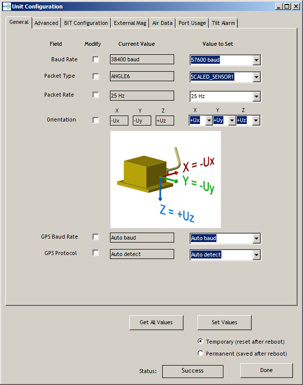
Unit Configuration
The Unit Configuration window (See Figure 4) gives the user the ability to view and alter the system settings. This window is accessed through the “Unit Configuration” menu item under the configuration menu. Under the “General” tab, users have the ability to verify the current configuration by selecting the “Get All Values” button. This button simply provides users with the currently set configuration of the unit and displays the values in the left column of boxes.
There are four tabs within the “Unit Configuration” menu; General, Advanced, BIT Configuration and tilt alarm. The General tab displays some of the most commonly used settings. The Advanced , BIT Configuration and tilt alarm menus provide users with more detailed setting information that they can tailor to meet their specific needs.
To alter a setting, simply select the check box on the left of the value that you wish to modify and then select the value using the drop down menu on the right side. Once you have selected the appropriate value, these settings can be set temporarily or permanently (a software reset or power cycle is required for the changes to take affect) by selecting from the choices at the bottom of the dialog box. Once the settings have been altered a “Success” box will appear at the bottom of the page.
IMPORTANT
Caution must be taken to ensure that the settings selected are compatible with the system that is being configured. In most cases a “FAIL” message will appear if incompatible selections are made by the user, however it is the users responsibility to ensure proper configuration of the unit.
IMPORTANT
Unit orientation selections must conform to the right hand coordinate system as noted in Section 4.1 of this user manual. Selecting orientations that do not conform to this criteria are not allowed.
- Unit Configuration
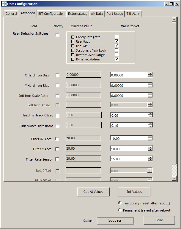
Advanced Configuration
Users who wish to access some of the more advanced features of NAV-VIEW and the MTLT1 Series products can do so by selecting the “Advanced” tab at the top of the “Unit Configuration” window.
WARNING
Users are strongly encouraged to read and thoroughly understand the consequences of altering the settings in the “Advanced” tab before making changes to the unit configuration. These settings are discussed in detail in Chapter 4 below.
Behavior switches are identified at the top of the page with marked boxes. A blue box will appear if a switch has been enabled similar to Figure 5 below. The values can be set in the same manner as noted in the previous section. To set a value, users select the appropriate “Modify” checkbox on the left side of the menu and select or enable the appropriate value they wish to set. At the bottom of the page, users have the option of temporarily or permanently setting values. When all selections have been finalized, simply press the “Set Values” button to change the selected settings.
- Advanced Settings
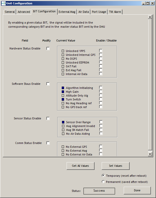
Bit Configuration
The third tab of the unit configuration window is “Bit Configuration” (See Figure 6). This tab allows the users to alter the logic of individual status flags that affect the masterStatus flag in the master BITstatus field (available in most output packets). By enabling individual status flags users can determine which flags are logically OR’ed to generate the masterStatus flag. This gives the user the flexibility to listen to certain indications that affect their specific application. The masterFail and all error flags are not configurable. These flags represent serious errors and should never be ignored.
- BIT Configuration
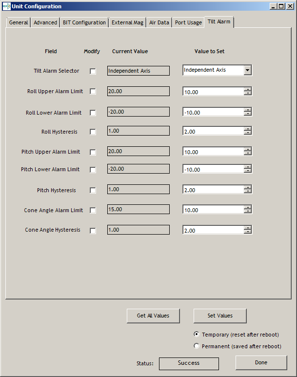
Tilt alarm
The final tab of the unit configuration window is “Tilt alarm” (See Figure 7). This tab allows the users to select alarm source and set alarm threshold angles with hysteresis.
Tilt alarm selector: independent roll/pitch or cone angle
Alarm limit: alarm upper and lower limits.
Hysteresis: alarm limit hysteresis
Figure 7. Tilt alarm
Read Unit Configuration
NAV-VIEW allows users to view the current settings and calibration data for a given MTLT Series unit by accessing the “Read Configuration” selection from the “Configuration” drop down menu (See Figure 8). From this dialog, users can print a copy of the unit’s current configuration and calibration values with the click of a button. Simply select the “Read” button at the top of the dialog box and upon completion select the “Print” or “Print Preview” buttons to print a copy to your local network printer. This information can be helpful when storing hard copies of unit configuration, replicating the original data sheet and for troubleshooting if you need to contact Aceinna’s Support Staff.
Figure 8. Read Configuration
Theory of Operation
This section of the manual covers detailed theory of operation for both the static and dynamic versions of the MTLT series family.
- MTLT1 Series Overview
| Product | Features | Learning More |
|---|---|---|
| MTLT1xxS | Accelerometer-based static tilt sensor | Read 4.1 and 4.2 |
| MTLT1xxD | Gyro-compensated dynamic tilt sensor | Read 4.1, 4.2 and 4.3 |
Figure 9 shows the MTLT Series hardware block diagram. At the core of the MTLT Series is a high-performance MEMS 3-axis accelerometer. The dynamic MTLT tilt sensors also include a 3-axis MEMS gyroscope used for linear acceleration compensation. These sensors are based on rugged, field proven silicon bulk micromachining technology. Each sensor within the cluster is individually factory calibrated using Aceinna’s automated manufacturing process. Sensor errors are compensated for temperature bias, scale factor, non-linearity and misalignment effects using a proprietary algorithm from data collected during manufacturing. Accelerometer, rate gyro, and magnetometer sensor bias shifts over temperature (-40 0C to +70 0C) are compensated and verified using calibrated thermal chambers and rate tables. The sensor data is fed into a high-speed microprocessor which calculates the roll and pitch data using our proprietary Kalman filters.
Figure 9. MTLT Series Hardware Block Diagram
Figure 10 shows the software block diagram. The accelerometer and gyro (dynamic only) sensor data is fed into a high speed 200Hz signal processing chain. Measurement data packets are available at fixed continuous output rates or on a polled basis.
Figure 10. MTLT Series Software Block Diagram
Figure 9 shows a simplified functional block diagrams for MTLT static and dynamic sensors. Dynamic sensors include a 3-axis gyro and take advantage of the Extended Kalman Filter. The common aiding sensor for the drift correction for the attitude (i.e., roll and pitch only) is a 3-axis accelerometer.
MTLT Series Default Coordinate System
The MTLT Series Inertial System default coordinate system is shown in Figure 11. As with many elements of the MTLT Series, the coordinate system is configurable with either NAV-VIEW or by sending the appropriate serial commands. These configurable elements are known as *Advanced Settings*. This section of the manual describes the default coordinate system settings of the MTLT Series when it leaves the factory.
With the MTLT Series product connector facing you, and the label facing up, the axes are defined as follows:
Figure 11. MTLT1 Series Default Coordinate System
x-axis – from face with connector through the MTLT unit
y-axis – along the face with connector from left to right
z-axis – along the face with the connector from top to bottom
The axes form an orthogonal SAE right-handed coordinate system. Acceleration is positive when it is oriented towards the positive side of the coordinate axis. For example, with a MTLT Series product sitting on a level table, it will measure zero g along the x- and y-axes and -1 g along the z-axis. Normal Force acceleration is directed upward, and thus will be defined as negative for the MTLT Series z-axis.
The angular rate sensors are aligned with these same axes. The rate sensors measure angular rotation rate around a given axis. The rate measurements are labeled by the appropriate axis. The direction of a positive rotation is defined by the right-hand rule. With the thumb of your right hand pointing along the axis in a positive direction, your fingers curl around in the positive rotation direction. For example, if the MTLT Series product is sitting on a level surface and you rotate it clockwise on that surface, this will be a positive rotation around the z-axis. The x- and y-axis rate sensors would measure zero angular rates, and the z-axis sensor would measure a positive angular rate.
Pitch is defined positive for a positive rotation around the y-axis (pitch up). Roll is defined as positive for a positive rotation around the x-axis (roll right). Yaw is defined as positive for a positive rotation around the z-axis (turn right).
The angles are defined as standard Euler angles using a 3-2-1 system. To rotate from the body frame to an earth-level frame, roll first, then pitch, and then yaw.
Advanced Settings
The MTLT Series Inertial Systems have a number of advanced settings that can be changed. All units support baud rate, power-up output packet type, output rate, sensor low pass filtering, tilt-alarm configurations, and custom axes configuration. The units can be configured using NAV-VIEW, as described in Section 3, and also directly with serial commands as described in Sections 6-9.
IMPORTANT
The Delta-Theta, Delta-V packet is only recommended for use in continuous output mode at 5Hz or greater. Polled requests for this packet will produce values accumulated since the last poll request, and thus, are subject to overflow (data type wrap around).
4.2 Dynamic MTLT Theory of Operation
The MTLT1xxD supports dynamic roll and pitch measurements that are stabilized by the using the accelerometers as a long-term gravity reference and gyro for dynamic motion compensation. At a fixed 200Hz rate, the MTLT1xxD continuously maintains both the calibrated sensor (accelerometer and gyro) data as well as the roll and pitch data. As shown in the software block diagram Figure 10, after the Sensor Calibration block, the sensor data is passed into an Integration to Orientation block. The Integration to Orientation block integrates body frame sensed angular rate to orientation at a fixed 200 times per second within all of the MTLT1xxD Series products. For improved accuracy and to avoid singularities when dealing with the cosine rotation matrix, a quaternion formulation is used in the algorithm to provide attitude propagation.
As also shown in the software block diagram, the Integration to Orientation block receives drift corrections from the Extended Kalman Filter or Drift Correction Module. In general, rate sensors and accelerometers suffer from bias drift, misalignment errors, acceleration errors (g-sensitivity), nonlinearity (square terms), and scale factor errors. The largest error in the orientation propagation is associated with the rate sensor bias terms. The Extended Kalman Filter (EKF) module provides an on-the-fly calibration for drift errors, including the rate sensor bias, by providing corrections to the Integration to Orientation block and a characterization of the gyro bias state. In the MTLT1xxD, the internally computed gravity reference vector provides a reference measurement for the EKF when the MTLT1xxD is in quasi-static motion to correct roll and pitch angle drift and to estimate the X and Y gyro rate bias. Because the gravity vector has no horizontal component, the EKF has no ability to estimate either the yaw angle error or the Z gyro rate bias. The MTLT1xxD adaptively tunes the EKF feedback in order to best balance the bias estimation and attitude correction with distortion free performance during dynamics when the object is accelerating either linearly (speed changes) or centripetally (false gravity forces from turns). Because centripetal and other dynamic accelerations are often associated with yaw rate, the MTLT1xxD maintains a low-passed filtered yaw rate signal and compares it to the turnSwitch threshold field (user adjustable). When the user platform to which the MTLT1xxD is attached exceeds the turnSwitch threshold yaw rate, the MTLT1xxD lowers the feedback gains from the accelerometers to allow the attitude estimate to coast through the dynamic situation with primary reliance on angular rate sensors. This situation is indicated by the softwareStatusturnSwitch status flag. Using the turn switch maintains better attitude accuracy during short-term dynamic situations, but care must be taken to ensure that the duty cycle of the turn switch generally stays below 10% during the vehicle mission. A high turn switch duty cycle does not allow the system to apply enough rate sensor bias correction and could allow the attitude estimate to become unstable.
The MTLT1xxD algorithm has two major phases of operation. The first phase of operation is the initialization phase. During the initialization phase, the MTLT1xxD is expected to be stationary or quasi-static so the EKF weights the accelerometer gravity reference heavily in order to rapidly estimate the roll and pitch angles, and X, Y rate sensor bias. The initialization phase lasts approximately 60 seconds, and the initialization phase can be monitored in the softwareStatus BIT transmitted by default in each measurement packet. After the initialization phase, the MTLT1xxD operates with lower levels of feedback (also referred to as EKF gain) from the accelerometers to continuously estimate and correct for roll and pitch errors, as well as to estimate X and Y rate sensor bias.
If a user wants to reset the algorithm or re-enter the initialization phase, sending the algorithm reset command, ‘AR’, will force the algorithm into the reset phase.
The MTLT1xxD outputs digital measurement data over the RS-232 serial link at a selectable fixed rate (100, 50, 25, 20, 10, 5 or 2 Hz) or on as requested basis using the GP, ‘Get Packet’ command.
4.2.1 MTLT1xxD Advanced Settings
In addition to the configurable baud rate, packet rate, axis orientation, and sensor low-pass filter settings, the MTLT1xxD provides additional advanced settings which are selectable for tailoring the MTLT1xxD to a specific application requirements. These MTLT1xxD advanced settings are shown in Table 10 below:
- MTLT1xxD Series Advanced Settings
| Setting | Default | Comments |
|---|---|---|
| Baud Rate | 38400 | 57600, 115200,23040
also available
|
| Packet Type | A6 | A7 also available |
| Packet Rate | 25Hz | This setting sets the
rate at which
selected Packet Type,
packets are output.
If polled mode is
desired, then select
Quiet. If Quiet is
selected, the
MTLT1xxD will only
send measurement
packets in response
to GP commands.
|
| Orientation | See Fig. 12 |
To configure the axis
orientation, select
the desired
measurement for each
axes: NAV-VIEW will
show the
corresponding image
of the MTLT1xxD, so
it easy to visualize
the mode of
operation. See
Section 8.4
Orientation Field
settings for the
twenty four possible
orientation settings.
The default setting
points the connector
AFT.
|
| Filter Settings (5, 10, 20, 50 Hz) | 20 Hz | The low pass filters
are set to a default
of 5Hz for the
accelerometers, and
20 Hz for the angular
rate sensors.
|
| Freely Integrate | OFF | The Freely Integrate
setting allows a user
to turn the MTLT1xxD
into a ‘free gyro’.
In free gyro mode,
the roll, pitch and
yaw are computed
exclusively from
angular rate with no
kalman filter based
corrections of roll,
pitch, or yaw. When
turned on, there is
no coupling of
acceleration based
signals into the roll
and pitch. As a
result, the roll,
pitch, and yaw
outputs will drift
roughly linearly with
time due to sensor
bias. For best
performance, the
Freely Integrate mode
should be used after
the algorithm has
initialized. This
allows the Kalman
Filter to estimate
the roll and pitch
rate sensor bias
prior to entering the
free gyro mode. Upon
exiting the ‘free
gyro’ mode (OFF), one
of two behaviors will
occur
(1) If the MTLT1xxD
has been in
freely integrate
mode for less
than sixty
seconds, the
algorithm will
resume operation
at normal gain
settings
(2) If the MTLT1xxD
has been in
freely integrate
mode for greater
than sixty
seconds, the
algorithm will
force a reset and
reinitialize with
high gains
automatically.
|
| Restart On Over Range | OFF | This setting forces
an algorithm reset
when a sensor over
range occurs i.e., a
rotational rate on
any of the three axes
exceeds the maximum
range. The default
setting is OFF for
the MTLT1xxD.
Algorithm reset
returns the MTLT1xxD
to a high gain state,
where the MTLT1xxD
rapidly estimates the
gyro bias and uses
the accelerometer
feedback heavily.
This setting is
recommended when the
source of over-range
is likely to be
sustained and
potentially much
greater than the rate
sensor operating
limit. Large and
sustained angular
rate over-ranges
result in
unrecoverable errors
in roll and pitch
outputs. An
unrecoverable error
is one where the EKF
can not stabilize the
resulting roll and
pitch reading. If the
over-ranges are
expected to be of
short duration (<1
sec) and a modest
percentage over the
maximum operating
range, it is
recommended that the
restart on over range
setting be turned
off. Handling of an
inertial rate sensor
over-range is
controlled using the
restartOnOverRange
switch. If this
switch is off, the
system will flag the
overRange status flag
and continue to
operate through it.
If this switch is on,
the system will flag
a masterFail error
during an over-range
condition and
continue to operate
with this flag until
a quasi-static
condition is met to
allow for an
algorithm restart.
The quasi-static
condition required is
that the absolute
value of each
low-passed rate
sensor fall below 3
deg/sec to begin
initialization. The
system will then
attempt a normal
algorithm start.
|
| Dynamic Motion | ON | The default setting
is ON for the
MTLT1xxD. Turning off
the dynamic motion
setting results in a
higher gain state
that uses the
accelerometer
feedback heavily.
During periods of
time when there is
known low dynamic
acceleration, this
switch can be turned
off to allow the
attitude estimate to
quickly stabilize.
|
| Turn Switch threshold | 10.0 deg/sec | With respect to
centripetal or false
gravity forces from
turning dynamics (or
coordinated turn),
the MTLT1xxD monitors
the yaw-rate. If the
yaw rate exceeds a
given Turnswitch
threshold, the
feedback gains from
the accelerometer
signals for attitude
correction are
reduced because they
are likely corrupted.
|
| BIT | See 4.3.2 |
4.2.2 MTLT1xxD Built-In Test
The MTLT1xxD Built-In Test capability allows users of the MTLT1xxD to monitor health, diagnostic, and system status information of the unit in real-time. The Built-In Test information consists of a BIT word (2 bytes) transmitted in every measurement packet. In addition, there is a diagnostic packet ‘T0’ that can be requested via the Get Packet ‘GP’ command which contains a complete set of status for each hardware and software subsystem in the MTLT1xxD. See Sections 6 and 7 for details on the ‘T0’ packet.
The BIT word contained within each measurement packet is detailed below. The LSB (Least Significant Bit) is the Error byte, and the MSB (Most Significant Bit) is a Status byte with programmable alerts. Internal health and status are monitored and communicated in both hardware and software. The ultimate indication of a fatal problem is the masterFail flag.
The masterStatus flag is a configurable indication that can be modified by the user. This flag is asserted as a result of any asserted alert signals which have been enabled. See Advanced BIT (Section 9) for details on configuring the masterStatus flags. Table 11 shows the BIT definition and default settings for BIT programmable alerts in the MTLT1xxD.
- MTLT1xxD Default BIT Status Definition
| BITstatus Field | Bits | Meaning | Category |
|---|---|---|---|
| masterFail | 0 | 0 = normal, 1 =
fatal error has
occurred
|
BIT |
| HardwareError | 1 | 0 = normal, 1=
internal
hardware error
|
BIT |
| comError | 2 | 0 = normal, 1 =| BIT
communication |
error |
|
|
| softwareError | 3 | 0 = normal, 1 =| BIT
internal |
software error |
|
|
| Reserved | 4:7 | N/A | |
| masterStatus | 8 | 0 = nominal, 1
= one or more
status alerts
|
Status |
| hardwareStatus | 9 | Disabled | Status |
| comStatus | 10 | 0 = nominal, 1
= No External
GPS Comm
|
Status |
| softwareStatus | 11 | 0 = nominal, 1
= Algorithm
Initialization
or High Gain
|
Status |
| sensorStatus | 12 | 0 = nominal, 1
=
|
Status |
| Reserved | 13:15 | N/A | |
The MTLT1xxD also allows a user to configure the Status byte within the BIT message. To configure the word, select the BIT Configuration tab from the Unit Configuration menu. The dialog box allows selection of which status types to enable (hardware, software, sensor, and comm). Aceinna recommends for the vast majority of users, that the default Status byte for the MTLT1xxD is sufficient. For users, who wish to have additional visibility to when the MTLT1xxD EFK algorithm estimates that the MTLT1xxD is turning about its Z or Yaw axis, the softwareStatus bit can be configured to go high during a turn. In other words, the turnSwitch will turn on the softwareStatus bit. In the MTLT1xxD, the turnSwitch is by default set at 10.0 deg/sec about the z-axis.
Tilt Alarm (Independent vs. Cone Angle)
In many safety applications, accurately determining if the vehicle or equipment is tilted beyond a certain safety threshold is the most important requirement. The MTLT1 series tilt sensors is designed by be an all-in-one solution for both static and dynamic safety solutions.
The user can select tilt alarm mode for independent pitch and roll angles or cone angle through NAV-VIEW. Independent and cone angle are show in Figure 12.
Figure 12. Independent & Cone Angle
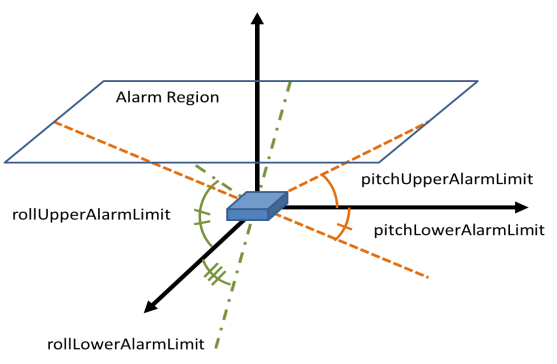
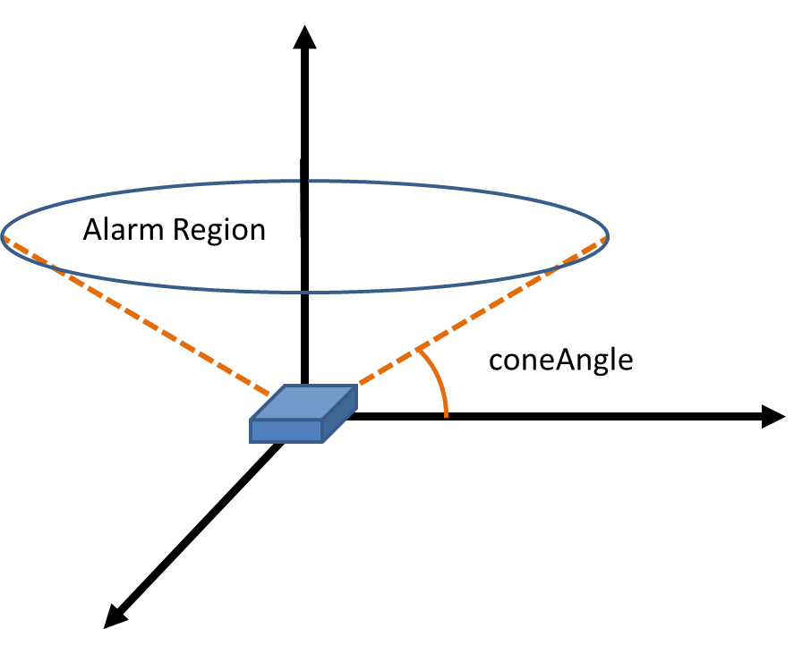
Independent Cone Angle
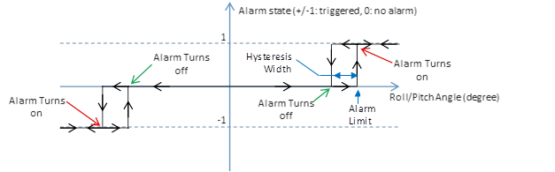
Hysteresis: if the tilt exceeds user definable alarm threshold, alarm will change to high and it will hold the high level until the angle is less than the user definable clear threshold. The clear threshold is not user definable value, user can get the clear threshold by calculation. the formula is : Clear value = +/-(ABS(alarm limit) - hysteresis). Hysteresis is shown in figure 13.
Figure 13: Hysteresis
Application Guide
Introduction
This section provides recommended advanced settings for tailoring the MTLT1 Series of tilt sensors to different types of application and platform requirements.
Equipment Leveling and lockout
MTLT can be used to level equipment or measure tilt while moving in heavy construction machinery, oil industry and so on.
The unit can be placed on the boom or chassis, for example, to measure tilt angle during moving or platform leveling. The measurement provides improved control while the alarm signal can be used for added protection and lockout.

In the oil industry, MTILT can be placed on a pumpjack to measure the walking beam angle change.

Aerial Work Platform Safety
To protect the safety of the operator, it is very important to control and correct the angle of the platform. MTLT can be used to measure and control the angle of the operator platform, chassis or boom. Multiple MTLT sensors can be used to measure the change of the angle between the chassis and boom. The alarm signal can be used for protection and lockout.

Land Vehicle
Payload imbalance can adversely affect handling and safety. More and more trucks use tilt sensors to optimize payload balance; increasing safety, improving fuel economy and minimizing wear of vehicle components.
Programming Guide
The MTLT1 Series contains a number of different products which have different measurement capabilities. Depending on the model you purchased, various commands and output modes are supported. However, all models support a common packet structure that includes both command or input data packets (data sent to the MTLT1 Series) and measurement output or response packet formats (data sent from the MTLT1 Series). This section of the manual explains these packet formats as well as the supported commands. NAV-VIEW also features a number of tools that can help a user understand the packet types available and the information contained within the packets. This section of the manual assumes that the user is familiar with ANSI C programming language and data type conventions.
For an example of the code required to parse input data packets, please see refer to Appendix C.
For qualified commercial OEM users, a source code license of NAV-VIEW can be made available under certain conditions. Please contact your Aceinna representative for more information.
General Settings
The serial port settings are RS232 with 1 start bit, 8 data bits, no parity bit, 1 stop bit, and no flow control. Standard baud rates supported are: 9600, 19200, 38400, and 57600.
Common definitions include:
- A word is defined to be 2 bytes or 16 bits.
- All communications to and from the unit are packets that start with a single word alternating bit preamble 0x5555. This is the ASCII string “UU”.
- All multiple byte values are transmitted Big Endian (Most Significant Byte First).
- All communication packets end with a single word CRC (2 bytes). CRC’s are calculated on all packet bytes excluding the preamble and CRC itself. Input packets with incorrect CRC’s will be ignored.
- Each complete communication packet must be transmitted to the MTLT1 Series tilt sensors within a 4 second period.
Number Formats
Number Format Conventions include:
- 0x as a prefix to hexadecimal values
- single quotes (‘’) to delimit ASCII characters
- no prefix or delimiters to specify decimal values.
Table 20 defines number formats:
- Number Formats
| Descriptor | Description | Size(bytes) | Comment | Range |
|---|---|---|---|---|
| U1 | Unsigned
Char
|
1 | 0 to 255 | |
| U2 | Unsigned
Short
|
2 | 0 to 65535 | |
| U4 | Unsigned
Int
|
4 | 0 to 2^32-1 | |
| I2 | Signed
Short
|
2 | 2’s
Complement
|
-2^15 to 2^15-1 |
| I2* | Signed
Short
|
2 | Shifted 2’s
Complement
|
Shifted to
specified
range
|
| I4 | Signed
Int
|
4 | 2’s
Complement
|
-2^31 to 2^31-1 |
| F4 | Floating
Point
|
4 | IEEE754
Single
Precision
|
-1*2^127 to 2^127 |
| SN | String | N | ASCII |
Packet Format
All of the Input and Output packets, except the Ping command, conform to the following structure:
| 0x5555 | <2-byte packet type (U2)> | <payload byte-length (U1)> | <variable length payload> | <2-byte CRC (U2)> |
The Ping Command does not require a CRC, so a MTLT1 Series unit can be pinged from a terminal emulator. To Ping a MTLT1 Series unit, type the ASCII string ‘UUPK’. If properly connected, the MTLT1 Series unit will respond with ‘PK’. All other communications with the MTLT1 Series unit require the 2-byte CRC. {Note: A MTLT1 Series unit will also respond to a ping command using the full packet formation with payload 0 and correctly calculated CRC. Example: 0x5555504B009ef4 }.
Packet Header
The packet header is always the bit pattern 0x5555.
Packet Type
The packet type is always two bytes long in unsigned short integer format. Most input and output packet types can be interpreted as a pair of ASCII characters. As a semantic aid consider the following single character acronyms:
P = packet
F = fields
Refers to Fields which are settings or data contained in the unit
E = EEPROM
Refers to factory data stored in EEPROM
R = read
Reads default non-volatile fields
G = get
Gets current volatile fields or settings
W = write
Writes default non-volatile fields. These fields are stored in non-volatile memory and determine the unit’s behavior on power up. Modifying default fields take effect on the next power up and thereafter.
S = set
Sets current volatile fields or settings. Modifying current fields will take effect immediately by modifying internal RAM and are lost on a power cycle.
Payload Length
The payload length is always a one byte unsigned character with a range of 0-255. The payload length byte is the length(in bytes) of the <variable length payload> portion of the packet ONLY, and does not include the CRC.
Payload
The payload is of variable length based on the packet type.
16-bit CRC-CCITT
Packets end with a 16-bit CRC-CCITT calculated on the entire packet excluding the 0x5555 header and the CRC field itself. A discussion of the 16-bit CRC-CCITT and sample code for implementing the computation of the CRC is included at the end of this document. This 16-bit CRC standard is maintained by the International Telecommunication Union (ITU). The highlights are:
Width = 16 bits
Polynomial 0x1021
Initial value = 0xFFFF
No XOR performed on the final value.
See Appendix C for sample code that implements the 16-bit CRC algorithm.
Messaging Overview
Table 21 summarizes the messages available by MTLT1 Series model. Packet types are assigned mostly using the ASCII mnemonics defined above and are indicated in the summary table below and in the detailed sections for each command. The payload byte-length is often related to other data elements in the packet as defined in the table below. The referenced variables are defined in the detailed sections following. Output messages are sent from the MTLT1 Series inertial system to the user system as a result of a poll request or a continuous packet output setting. Input messages are sent from the user system to the MTLT1 Series inertial system and will result in an associated Reply Message or NAK message. Note that reply messages typically have the same *<2-byte packet type (U2)>* as the input message that evoked it but with a different payload.
- Message Table
ASCII
Mnemonic
|
<2-byte
packet
type
(U2)>
|
<payload
byte-
length
(U1)>
|
Description | Type | Products
Available
|
|---|---|---|---|---|---|
| Link Test | |||||
| PK | 0x504B | 0 | Ping
Command
and
Response
|
Input/
Reply
Message
|
ALL |
| CH | 0x4348 | N | Echo
Command
and
Response
|
Input/
Reply
Message
|
ALL |
Interactive
Commands
|
|||||
| GP | 0x4750 | 2 | Get
Packet
Request
|
Input
Message
|
ALL |
| AR | 0x4152 | 0 | Algorithm
Reset
|
Input/
Reply
Message
|
ALL |
| NAK | 0x1515 | 2 | Error
Response
|
Reply
Message
|
ALL |
Output
Messages:
Status &
Other,
(Polled
Only)
|
|||||
| ID | 0x4944 | 5+N | ID data | Output
Message
|
ALL |
| VR | 0x5652 | 5 | Version
Data
|
Output
Message
|
ALL |
| T0 | 0x5430 | 28 | Test 0
(Detailed
BIT and
Status)
|
Output
Message
|
ALL |
Output
Messages:
Measurement
Data
(Continuous
or polled)
|
|||||
| A6 | Angle 6
Data
|
Output
Message
|
ALL | ||
| A7 | Angle 7
Data
|
Output
Message
|
ALL | ||
Advanced
Commands
|
|||||
| WF | 0x5746 | numFields
*4+1
|
Write
Fields
Request
|
Input
Message
|
ALL |
| WF | 0x5746 | numFields
*2+1
|
Write
Fields
Response
|
Reply
Message
|
ALL |
| SF | 0x5346 | numFields
*4+1
|
Set
Fields
Request
|
Input
Message
|
ALL |
| SF | 0x5346 | numFields
*2+1
|
Set
Fields
Response
|
Reply
Message
|
ALL |
| RF | 0x5246 | numFields
*2+1
|
Read
Fields
Request
|
Input
Message
|
ALL |
| RF | 0x5246 | numFields
*4+1
|
Read
Fields
Response
|
Reply
Message
|
ALL |
| GF | 0x4746 | Get
Fields
Request
|
Input
Message
|
ALL | |
| GF | 0x4746 | numFields
*4+1
|
Get
Fields
Response
|
Reply
Message
|
ALL |
Communicating with the MTLT1 Series
Link Test.
Ping Command
| Ping (‘PK’ = 0x504B) | |||
| Preamble | Packet Type | Length | Termination |
| 0x5555 | 0x504B |
The ping command has no payload. Sending the ping command will cause the unit to send a ping response. To facilitate human input from a terminal, the length and CRC fields are not required. (Example: 0x5555504B009ef4 or 0x5555504B))
Ping Response
| Ping (‘PK’ = 0x504B) | |||
| Preamble | Packet Type | Length | Termination |
| 0x5555 | 0x504B | 0x00 | <CRC (U2)> |
The unit will send this packet in response to a ping command.
Echo Command
| Echo (‘CH’ = 0x4348) | ||||
| Preamble | Packet Type | Length | Payload | Termination |
| 0x5555 | 0x4348 | N | <echo payload> | <CRC (U2)> |
The echo command allows testing and verification of the communication link. The unit will respond with an echo response containing the echo data. The echo data is N bytes long.
Echo Response
| Echo Payload | |||||
|---|---|---|---|---|---|
| Byte Offset | Name | Format | Scaling | Units | Description |
| 0 | echoData0 | U1 | first
byte of
echo data
|
||
| 1 | echoData1 | U1 | Second
byte of
echo data
|
||
| … | … | U1 | Echo data | ||
| N-2 | echoData. .. | U1 | Second to
last byte
of echo
data
|
||
| N-1 | echoData… | U1 | Last byte
of echo
data
|
Interactive Commands
Interactive commands are used to interactively request data from the MTLT1 Series, and to calibrate or reset the MTLT1 Series.
Get Packet Request
| Get Packet (‘GP’ = 0x4750) | ||||
| Preamble | Packet Type | Length | Payload | Termination |
| 0x5555 | 0x4750 | 0x02 | <GP payload> | <CRC (U2)> |
This command allows the user to poll for both measurement packets and special purpose output packets including ‘T0’, ‘VR’, and ‘ID’.
| GP Payload | |||||
|---|---|---|---|---|---|
| Byte Offset | Name | Format | Scaling | Units | Description |
| 0 | requested PacketTyp e | U2 | The
requested
packet
type
|
Refer to the sections below for Packet Definitions sent in response to the ‘GP’ command
Algorithm Reset Command
| Algorithm Reset (‘AR’ = 0x4152) | ||||
| Preamble | Packet Type | Length | Payload | Termination |
| 0x5555 | 0x4152 | 0x00 | <CRC (U2)> |
This command resets the state estimation algorithm without reloading fields from EEPROM. All current field values will remain in affect. The unit will respond with an algorithm reset response.
Algorithm Reset Response
| Algorithm Reset (‘AR’ = 0x4152) | |||
| Preamble | Packet Type | Length | Termination |
| 0x5555 | 0x4152 | 0x00 | <CRC (U2)> |
The unit will send this packet in response to an algorithm reset command.
Error Response
Error
Response
(ASCII NAK,
NAK =
0x1515)
|
||||
| Preamble | Packet Type | Length | Payload | Termination |
| 0x5555 | 0x1515 | 0x02 | <NAK payload> | <CRC (U2)> |
The unit will send this packet in place of a normal response to a faiiledInputPacketType request if it could not be completed successfully.
NAK
Payload
Contents
|
|||||
|---|---|---|---|---|---|
| Byte Offset | Name | Format | Scaling | Units | Description |
| 0 | failedInp utPacketT ype | U2 | the
failed
request
|
Output Packets (Polled)
The following packet formats are special informational packets which can be requested using the ‘GP’ command.
Identification Data Packet
Identification
Data (‘ID’
= 0x4944)
|
||||
| Preamble | Packet Type | Length | Payload | Termination |
| 0x5555 | 0x4944 | 5+N | <ID payload> | <CRC (U2)> |
This packet contains the unit serialNumber and modelString. The model string is terminated with 0x00. The model string contains the programmed versionString (8-bit Ascii values) followed by the firmware part number string delimited by a whitespace.
| ID Payload Contents | |||||
|---|---|---|---|---|---|
| Byte Offset | Name | Format | Scaling | Units | Description |
| 0 | serialNumber | U4 | Unit serial number | ||
| 4 | modelString | SN | Unit Version String | ||
| 4+N | 0x00 | U1 | Zero Delimiter |
Version Data Packet
| Version Data (‘VR’ = 0x5652) | ||||
| Preamble | Packet Type | Length | Payload | Termination |
| 0x5555 | 0x5652 | 5 | <VR payload> | <CRC (U2)> |
This packet contains firmware version information. majorVersion changes may introduce serious incompatibilities. minorVersion changes may add or modify functionality, but maintain backward compatibility with previous minor versions. patch level changes reflect bug fixes and internal modifications with little effect on the user. The build stage is one of the following: 0=release candidate, 1=development, 2=alpha, 3=beta. The buildNumber is incremented with each engineering firmware build. The buildNumber and stage for released firmware are both zero. The final beta candidate is v.w.x.3.y, which is then changed to v.w.x.0.1 to create the first release candidate. The last release candidate is v.w.x.0.z, which is then changed to v.w.x.0.0 for release.
| VR Payload | |||||
|---|---|---|---|---|---|
| Byte Offset | Name | Format | Scaling | Units | Description |
| 0 | major
verion
|
U1 | Major
firmware
version
|
||
| 1 | minor
version
|
U1 | Minor
firmware
version
|
||
| 2 | patch | U1 | Patch
level
|
||
| 3 | stage | Development
Stage
(0=release
candidate,
1=develop
2=alpha,
3=beta)
|
|||
| 4 | build number | U1 | Build
number
|
Test 0 (Detailed BIT and Status) Packet
| Test (‘T0’ = 0x5430) | ||||
| Preamble | Packet Type | Length | Payload | Termination |
| 03.3x5555 | 0x5430 | 0x1C | <T0 payload> | <CRC (U2)> |
This packet contains detailed BIT and status information. The full BIT Status details are described in Section 9 of this manual.
| T0 Payload | |||||
|---|---|---|---|---|---|
| Byte Offset | Name | Format | Scaling | Units | Description |
| 0 | BITstatus | U2 | Master
BIT and
Status
Field
|
||
| 2 | hardware BIT | U2 | Hardware BIT Field | ||
| 4 | hardware PowerBIT | U2 | Hardware
Power BIT
Field
|
||
| 6 | hardware
Environme
ntal |BIT |
U2 | Hardware
Environment
al | BIT Field |
||
| 8 | comBIT | U2 |
|
||
| 10 | comSerial
ABIT
|
U2 | Communicati
on | Serial A | BIT Field |
||
| 12 | comSerial
BBIT
|
U2 | Communicati
on | Serial B | BIT Field |
||
| 14 | software
BIT
|
U2 | Software
BIT Field
|
||
| 16 | software
Algorithm
BIT
|
U2 | Software
Algorithm
BIT Field
|
||
| 18 | software
DataBIT
|
U2 | Software
Data BIT
Field
|
||
| 20 | hardware
Status
|
U2 | Hardware
Status
Field
|
||
| 22 | comStatus | U2 | Communicati
on | Status | Field |
||
| 24 | software
Status
|
U2 | Software
Status
Field
|
||
| 26 | sensor
Status
|
U2 | Sensor
Status
Field
|
Output Packets (Polled or Continuous)
Angle Data Packet 6 (Default Data)
Angle Data
(‘A6’ =
0x4132)
|
||||
| Preamble | Packet Type | Length | Payload | Termination |
| 0x5555 | 0x4136 | 0x0A | <A6 payload> | <CRC (U2)> |
This packet contains angle data. Data involving angular measurements include the factor pi in the scaling and can be interpreted in either radians or degrees.
Angles: scaled to a range of [-pi,+pi) or [-180 deg to +180 deg).
| A6 Payload | |||||
|---|---|---|---|---|---|
| Byte Offset | Name | Format | Scaling | Units |
n |
| 0 | rollAngle | I2 | 2*pi/2^16 [360°/2^1 6] |
Radians [°] |
Roll angle |
| 2 | pitchAngle | I2 | 2*pi/2^16 [360°/2^1 6] |
Radians [°] |
Pitch angle |
| 4 | timeITOW | U4 | 1 | ms | DMU ITOW
(sync to
GPS)
Not
Implemented |
| 8 | BITstatus | U2 | Master
BIT and
Status
|
Angle Data Packet 7
| Angle Data (‘A7’ = 0x4137) | ||||
| Preamble | Packet Type | Length | Payload | Termination |
| 0x5555 | 0x4137 | 0x10 | <A7 payload> | <CRC (U2)> |
This packet contains angle data and selected sensor data scaled in most cases to a signed 2^16 2’s complement number. Data involving angular measurements include the factor pi in the scaling and can be interpreted in either radians or degrees.
Angles: scaled to a range of [-pi,+pi) or [-180 deg to +180 deg).
Accelerometers: scaled to a range of [-10,+10) g
| A7 Payload | |||||
|---|---|---|---|---|---|
| Byte Offset | Name | Format | Scaling | Units | Description |
| 0 | rollAngle | I2 | 2*pi/2^16 [360°/2^1 6] |
Radians [°] |
Roll angle |
| 2 | pitchAngl e | I2 | 2*pi/2^16 [360°/2^1 6] |
Radians [°] |
Pitch angle |
| 4 | xAccel | I2 | 20/2^16 | g | X
accelerom
eter |
| 6 | yAccel | I2 | 20/2^16 | g | Y
accelerom
eter |
| 8 | zAccel | I2 | 20/2^16 | g | Z
accelerom
eter |
| 10 | timeITOW | U4 | 1 | ms | DMU ITOW
(sync to
GPS)
Not
Implemented
|
| 14 | BITstatus | U2 | Master
BIT and
Status
|
Advanced Commands
The advanced commands allow users to programmatically change the MTLT1 Series settings. This section of the manual documents all of the settings and options contained under the Unit Configuration tab within NAV-VIEW. Using these advanced commands, a user’s system can change or modify the settings without the need for NAV-VIEW.
Configuration Fields
Configuration fields determine various behaviors of the unit that can be modified by the user. These include settings like baud rate, packet output rate and type, algorithm type, etc. These fields are stored in EEPROM and loaded on power up. These fields can be read from the EEPROM using the ‘RF’ command. These fields can be written to the EEPROM affecting the default power up behavior using the ‘WF’ command. The current value of these fields (which may be different from the value stored in the EEPROM) can also be accessed using the ‘GF’ command. All of these fields can also be modified immediately for the duration of the current power cycle using the ‘SF’ command. The unit will always power up in the configuration stored in the EEPROM. Configuration fields can only be set or written with valid data from Table 22 below.
- Configuration Fields
| configuration fields | field ID | Valid Values Values** | description |
Packet rate
divider
|
0x0001 | 0,1,2,4,5,10,20
25, 50
|
quiet, 100Hz,
50Hz, 25Hz,
20Hz, 10Hz,
5Hz, 4Hz,2Hz
|
Unit BAUD
rate
|
0x0002 | ,2,3,5,6 | 38400, 57600
115200, 230400
|
Continuous
packet type
|
0x0003 | Any output
packet type
|
Not all output
packets
available for
all products.
See detailed
product
descriptions.
|
| Unused | 0x0004 | ||
Gyro Filter
Setting
|
0x0005 | 7142-65535 [5Hz] 3571-7141 [10Hz] 1530-3570 [20Hz] 0-1529 [50 Hz] | Sets low pass
cutoff for rate
sensors. Cutoff
Frequency
choices are 5,
10, 20, and
50Hz
|
Accelerometer
Filter Setting
|
0x0006 | 7142-65535 [5Hz] 3571-7141 [10Hz] 1530-3570 [20Hz] 0-1529 [50 Hz] | Sets low pass
cutoff for
accelerometers.
Cutoff
Frequency
choices are 5,
10, 20, and
50Hz
|
| Orientation | 0x0007 | See below | Determine
forward,
rightward, and
downward facing
sides
|
User Behavior
Switches
|
0x0008 | Any | Free Integrate
(60 seconds),
Use Mags, Use
GPS, Stationary
Yaw Lock, …
|
Roll upper
alarm angle
|
0x0029 | [-25,25](deg) | Roll upper
alarm limit
|
Roll lower
alarm angle
|
0x002A | [-25,25](deg) | Roll lower
alarm limit
|
Pitch upper
alarm angle
|
0x002B | [-25,25](deg) | Pitch upper
alarm limit
|
Pitch lower
alarm angle
|
0x002C | [-25,25](deg) | Pitch lower
alarm limit
|
| Roll hysteresis | 0x002D | [1,3](deg) | Hysteresis for
roll alarm
|
Pitch
hysteresis
|
0x002E | [1,3](deg) | Hysteresis for
pitch alarm
|
| Alarm selector | 0x002F | 0,1 | Independent
angle, cone
angle
|
Cone angle
limit
|
0x0030 | [-25,25](deg) | Cone alarm
limit
|
Cone angle
hysteresis
|
0x0031 | [1,3](deg) | Hysteresis for
cone angle
|
Note: BAUD rate SF has immediate effect. Some output data may be lost. Response will be received at new BAUD rate.
Continuous Packet Type Field
This is the packet type that is being continually output. The supported packet depends on the model number. Please refer to Section 6.4 for a complete list of the available packet types.
Digital Filter Settings
These two fields set the digital low pass filter cutoff frequencies (See Table 23). Each sensor listed is defined in the default factory orientation. Users must consider any additional rotation to their intended orientation.
- Digital Filter Settings
| Filter Setting | Sensor |
|---|---|
| FilterGyro | Ux,Uy,Uz Rate |
| FilterAccel | Ux,Uy,Uz Accel |
Orientation Field
This field defines the rotation from the factory to user axis sets. This rotation is relative to the default factory orientation (connector aft, baseplate down). The default factory axis setting for the MTLT1 orientation field is (-Ux, -Uy, +Uz) as shown in Figure 15 below. With this default orientation, +X is defined as opposite where the connector is pointing, +Z is down through the base, and +Y is created by making the final orthogonal axis right-hand-rule. The user axis set is (X, Y, Z) as defined by this default orientation field loaded at the factory, but this can be changed as per Table 24.
Figure 15. MTLT1 Orientation Field (0x0009)
- MTLT1 Orientation Definitions
| Description | Bits | Meaning |
|---|---|---|
| X Axis Sign | 0 | 0 = positive, 1 = negative |
| X Axis | 1:2 | 0 = Ux, 1 = Uy, 2 = Uz, 3 = N/A |
| Y Axis Sign | 3 | 0 = positive, 1 = negative |
| Y Axis | 4:5 | 0 = Uy, 1 = Uz, 2 = Ux, 3 = N/A |
| Z Axis Sign | 6 | 0 = positive, 1 = negative |
| Z Axis | 7:8 | 0 = Uz, 1 = Ux, 2 = Uy, 3 = N/A |
| Reserved | 9:15 | N/A |
There are 24 possible orientation configurations (See Table 25). Setting/Writing the field to anything else generates a NAK and has no effect.
- MTLT1 Orientation Fields
| Orientation Field Value | X Axis | Y Axis | Z Axi* |
|---|---|---|---|
| 0x0000 | +Ux | +Uy | +Uz |
| 0x0009 | -Ux | -Uy | +Uz |
| 0x0023 | -Uy | +Ux | +Uz |
| 0x002A | +Uy | -Ux | +Uz |
| 0x0041 | -Ux | +Uy | -Uz |
| 0x0048 | +Ux | -Uy | -Uz |
| 0x0062 | +Uy | +Ux | -Uz |
| 0x006B | -Uy | -Ux | -Uz |
| 0x0085 | -Uz | +Uy | +Ux |
| 0x008C | +Uz | -Uy | +Ux |
| 0x0092 | +Uy | +Uz | +Ux |
| 0x009B | -Uy | -Uz | +Ux |
| 0x00C4 | +Uz | +Uy | -Ux |
| 0x00CD | -Uz | -Uy | -Ux |
| 0x00D3 | -Uy | +Uz | -Ux |
| 0x00DA | +Uy | -Uz | -Ux |
| 0x0111 | -Ux | +Uz | +Uy |
| 0x0118 | +Ux | -Uz | +Uy |
| 0x0124 | +Uz | +Ux | +Uy |
| 0x012D | -Uz | -Ux | +Uy |
| 0x0150 | +Ux | +Uz | -Uy |
| 0x0159 | -Ux | -Uz | -Uy |
| 0x0165 | -Uz | +Ux | -Uy |
| 0x016C | +Uz | -Ux | -Uy |
User Behavior Switches
This field allows on the fly user interaction with behavioral aspects of the algorithm (See Figure 26).
- MTLT1 Behavior Switches
| Description | Bits | Meaning |
|---|---|---|
| Free Integrate | 0 | 0 = use feedback to
stabilize the
algorithm, 1 = 6DOF
inertial integration
without stabilized
feedback for 60
seconds
|
| Use Mags | 1 | N/A |
| Use GPS | 2 | N/A |
| Stationary Yaw Lock | 3 | N/A |
| Restart on Over-range | 4 | 0 = Do not restart
the system after a
sensor over-range, 1
= restart the system
after a sensor
over-range
|
| Dynamic Motion | 5 | 0=vehicle is static,
force high gain
corrections, 1=
vehicle is dynamic,
use nominal
corrections
|
| Reserved | 6:15 | N/A |
Tilt alarm
The fields from 0x0029 to 0x0031 allow the users to select alarm source and set alarm threshold angles with hysteresis.
Commands to Program Configuration
Write Fields Command
Write
Fields
(‘WF’ =
0x5746)
|
||||
| Preamble | Packet Type | Length | Payload | Termination |
| 0x5555 | 0x5746 | 1+numFields *4 | <WF payload> | <CRC (U2)> |
This command allows the user to write default power-up configuration fields to the EEPROM. Writing the default configuration will not take affect until the unit is power cycled. NumFields is the number of words to be written. The field0, field1, etc. are the field
IDs that will be written with the field0Data, field1Data, etc., respectively. The unit will not write to calibration or algorithm fields. If at least one field is successfully written, the unit will respond with a write fields response containing the field IDs of the successfully written fields. If any field is unable to be written, the unit will respond with an error response. Note that both a write fields and an error response may be received as a result of a write fields command. Attempts to write a field with an invalid value is one way to generate an error response. A table of field IDs and valid field values is available in Section 8.1.
| WF Payload | |||||
|---|---|---|---|---|---|
| Byte Offset | Name | Format | Scaling | Units |
on |
| 0 | numFields | U1 | The
number of
fields to
write
|
||
| 1 | field0 | U2 | The first
field ID
to write
|
||
| 3 |
a |
U2 | The first
field
ID’s data
to write
|
||
| 5 | field1 | U2 | The
second
field ID
to write
|
||
| 7 |
a |
U2 | The
second
field
ID’s data
|
||
| … | … | U2 | … | ||
| numFields *4 -3 | field… | U2 | The last
field ID
to write
|
||
| numFields *4 -1 |
a |
U2 | The last
field
ID’s data
to write
|
*Write Fields Response*
Write
Fields
(‘WF’ =
0x5746)
|
||||
| Preamble | Packet Type | Length | Payload | Termination |
| 0x5555 | 0x5746 | 1+numFields *2 | <WF payload> | <CRC (U2)> |
The unit will send this packet in response to a write fields command if the command has completed without errors.
| WF Payload | |||||
|---|---|---|---|---|---|
| Byte Offset | Name | Format | Scaling | Units | Descripti on |
| 0 | numFields | U1 | The
number of
fields
written
|
||
| 1 | field0 | U2 | The first
field ID
written
|
||
| 3 | field1 | U2 | The
second
field ID
written
|
||
| … | … | U2 | More
field IDs
written
|
||
| numFields *2 – 1 | Field… | U2 | The last
field ID
written
|
Set Fields Command
Set Fields
(‘SF’ =
0x5346)
|
||||
| Preamble | Packet Type | Length | Payload | Termination |
| 0x5555 | 0x5346 | 1+numFields *4 | <SF payload> | <CRC (U2)> |
This command allows the user to set the unit’s current configuration (SF) fields immediately which will then be lost on power down. NumFields is the number of words to be set. The field0, field1, etc. are the field IDs that will be written with the field0Data, field1Data, etc., respectively. This command can be used to set configuration fields. The unit will not set calibration or algorithm fields. If at least one field is successfully set, the unit will respond with a set fields response containing the field IDs of the successfully set fields. If any field is unable to be set, the unit will respond with an error response. Note that both a set fields and an error response may be received as a result of one set fields command. Attempts to set a field with an invalid value is one way to generate an error response. A table of field IDs and valid field values is available in Section 8.1.
| SF Payload | |||||
|---|---|---|---|---|---|
| Byte Offset | Name | Format | Scaling | Units |
ion* |
| 0 | numFields | U1 | The
number of
fields to
set
|
||
| 1 | field0 | U2 | The first
field ID
to set
|
||
| 3 |
a |
U2 | The first
field
ID’s data
to set
|
||
| 5 | field1 | U2 | The
second
field ID
to set
|
||
| 7 |
a |
U2 | The
second
field
ID’s data
to set
|
||
| … | … | U2 | … | ||
| numFields *4 -3 | field… | U2 | The last
field ID
to set
|
||
| numFields *4 -1 |
|
U2 | The last
field
ID’s data
to set
|
*Set Fields Response*
Set Fields
(‘SF’ =
0x5346)
|
||||
| Preamble | Packet Type | Length | Payload |
n* |
| 0x5555 | 0x5346 | 1+numFields *2 | <SF payload> | <CRC (U2)> |
The unit will send this packet in response to a set fields command if the command has completed without errors.
| SF Payload | |||||
|---|---|---|---|---|---|
| Byte Offset | Name | Format | Scaling | Units |
ion* |
| 0 | numFields | U1 | The
number of
fields
set
|
||
| 1 | field0 | U2 | The first
field ID
set
|
||
| 3 | field1 | U2 | The
second
field ID
set
|
||
| … | … | U2 | More
field IDs
set
|
||
| numFields *2 - 1 | Field… | U2 | The last
field ID
set
|
Read Fields Command
Read Fields
(‘RF’ =
0x5246)
|
||||
| Preamble | Packet Type | Length | Payload |
n* |
| 0x5555 | 0x5246 | 1+numFields *2 | <RF payload> | <CRC (U2)> |
This command allows the user to read the default power-up configuration fields from the EEPROM. NumFields is the number of fields to read. The field0, field1, etc. are the field IDs to read. RF may be used to read configuration and calibration fields from the EEPROM. If at least one field is successfully read, the unit will respond with a read fields response containing the field IDs and data from the successfully read fields. If any field is unable to be read, the unit will respond with an error response. Note that both a read fields and an error response may be received as a result of a read fields command.
| RF Payload | |||||
|---|---|---|---|---|---|
| Byte Offset | Name | Format | Scaling | Units |
on* |
| 0 | numFields | U1 | The
number of
fields to
read
|
||
| 1 | field0 | U2 | The first
field ID
to read
|
||
| 3 | field1 | U2 | The
second
field ID
to read
|
||
| … | … | U2 | More
field IDs
to read
|
||
| numFields *2 - 1 | Field… | U2 | The last
field ID
to read
|
Read Fields Response
Read Fields
(‘RF’ =
0x5246)
|
||||
| Preamble | Packet Type | Length | Payload |
n* |
| 0x5555 | 0x5246 | 1+numFields *4 | <RF payload> | <CRC (U2)> |
The unit will send this packet in response to a read fields request if the command has completed without errors.
| RF Payload | |||||
|---|---|---|---|---|---|
| Byte Offset | Name | Format | Scaling | Units |
ion* |
| 0 | numFields | U1 | The
number of
fields
read
|
||
| 1 | field0 | U2 | The first
field ID
read
|
||
| 3 | field0Dat a | U2 | The first
field
ID’s data
read
|
||
| 5 | field1 | U2 | The
second
field ID
read
|
||
| 7 | field1Dat a | U2 | The
second
field
ID’s data
read
|
||
| … | … | U2 | … | ||
| numFields *4 -3 | field… | U2 | The last
field ID
read
|
||
| numFields *4 -1 | field…Dat a | U2 | The last
field
ID’s data
read
|
Get Fields Command
Get Fields
(‘GF’ =
0x4746)
|
||||
| Preamble | Packet Type | Length | Payload |
n* |
| 0x5555 | 0x4746 | 1+numFields *2 | <GF Data> | <CRC (U2)> |
This command allows the user to get the unit’s current configuration fields. NumFields is the number of fields to get. The field0, field1, etc. are the field IDs to get. GF may be used to get configuration, calibration, and algorithm fields from RAM. Multiple algorithm fields will not necessarily be from the same algorithm iteration. If at least one field is successfully collected, the unit will respond with a get fields response with data containing the field IDs of the successfully received fields. If any field is unable to be received, the unit will respond with an error response. Note that both a get fields and an error response may be received as the result of a get fields command.
| GF Payload | |||||
|---|---|---|---|---|---|
| Byte Offset | Name | Format | Scaling | Units |
n |
| 0 | numFields | U1 | The
number of
fields to
get
|
||
| 1 | field0 | U2 | The first
field ID
to get
|
||
| 3 | field1 | U2 | The
second
field ID
to get
|
||
| … | … | U2 | More
field IDs
to get
|
||
| numFields *2 – 1 | Field… | U2 | The last
field ID
to get
|
Get Fields Response
| Get Fields (‘GF’ = 0x4746) | ||||
| Preamble | Packet Type | Length | Payload | Termination |
| 0x5555 | 0x4746 | 1+numFields*4 | <GF Data> | <CRC (U2)> |
The unit will send this packet in response to a get fields request if the command has completed without errors.
| GF Payload | |||||
|---|---|---|---|---|---|
| Byte Offset | Name | Format | Scaling | Units |
n |
| 0 | numFields | U1 | The
number of
fields
retrieved
|
||
| 1 | field0 | U2 | The first
field ID
retrieved
|
||
| 3 | field0Dat a | U2 | The first
field
ID’s data
retrieved
|
||
| 5 | field1 | U2 | The
second
field ID
retrieved
|
||
| 7 | field1Dat a | U2 | The
second
field
ID’s data
|
||
| … | … | U2 | … | ||
| numFields *4 -3 | field… | U2 | The last
field ID
retrieved
|
||
| numFields *4 -1 | field…Dat a | U2 | The last
field
ID’s data
retrieved
|
Advanced BIT
Built In Test (BIT) and Status Fields
Internal health and status are monitored and communicated in both hardware and software. The ultimate indication of a fatal problem is a hardware BIT signal on the user connector which is mirrored in the software BIT field as the masterFail flag. This flag is thrown as a result of a number of instantly fatal conditions (known as a “hard” failure) or a persistent serious problem (known as a “soft” failure). Soft errors are those which must be triggered multiple times within a specified time window to be considered fatal. Soft errors are managed using a digital high-pass error counter with a trigger threshold.
The masterStatus flag is a configurable indication as determined by the user. This flag is asserted as a result of any asserted alert signals which the user has enabled.
The hierarchy of BIT and Status fields and signals is depicted here:
- BITstatus Field
- masterFail
- hardwareError
- hardwareBIT Field
- powerError
- hardwarePowerBIT Field
- inpPower
- inpCurrent
- inpVoltage
- fiveVolt
- threeVolt
- twoVolt
- twoFiveRef
- sixVolt
- grdRef
- hardwarePowerBIT Field
- environmentalError
- hardwareEnvironmentalBIT Field
- pcbTemp
- hardwareEnvironmentalBIT Field
- powerError
- hardwareBIT Field
- comError
- comBIT Field
- serialAError
- comSerialABIT Field
- transmitBufferOverflow
- receiveBufferOverflow
- framingError
- breakDetect
- parityError
- comSerialABIT Field
- serialBError
- comSerialBBIT Field
- transmitBufferOverflow
- receiveBufferOverflow
- framingError
- breakDetect
- parityError
- comSerialBBIT Field
- serialAError
- comBIT Field
- softwareError
- *softwareBIT Field *
- algorithmError
- softwareAlgorithmBIT Field
- initialization
- overRange
- missedIntegrationStep
- softwareAlgorithmBIT Field
- dataError
- softwareDataBIT Field
- calibrationCRCError
- magAlignOutOfBounds
- softwareDataBIT Field
- algorithmError
- *softwareBIT Field *
- hardwareError
- masterStatus
- hardwareStatus
- hardwareStatus Field
- unlocked1PPS (N/A)
- unlockedInternalGPS (N/A)
- noDGPS (N/A)
- unlockedEEPROM
- hardwareStatus Field
- comStatus
- comStatus Field
- noExternalGPS (Default)
- comStatus Field
- softwareStatus
- softwareStatus Field
- algorithmInitialization (enabled by default)
- highGain (enabled by default)
- attitudeOnlyAlgorithm
- turnSwitch
- softwareStatus Field
- sensorStatus
- sensorStatus Field
- overRange (enabled by default)
- sensorStatus Field
- hardwareStatus
- masterFail
Master BIT and Status (BITstatus) Field
The BITstatus field is the global indication of health and status of the MTLT1 Series product (See Table 29). The LSB contains BIT information and the MSB contains status information.
There are four intermediate signals that are used to determine when masterFail and the hardware BIT signal are asserted. These signals are controlled by various systems checks in software that are classified into three categories: hardware, communication, and software. Instantaneous soft failures in each of these four categories will trigger these intermediate signals, but will not trigger the masterFail until the persistency conditions are met.
There are four intermediate signals that are used to determine when the masterStatus flag is asserted: hardwareStatus, sensorStatus, comStatus, and softwareStatus. masterStatus is the logical OR of these intermediate signals. Each of these intermediate signals has a separate field with individual indication flags. Each of these indication flags can be enabled or disabled by the user. Any enabled indication flag will trigger the associated intermediate signal and masterStatus flag.
- MTLT1 BIT Status Field
| BITstatus Field | Bits | Meaning | Category |
|---|---|---|---|
| masterFail | 0 | 0 = normal, 1 =
fatal error has
occurred
|
BIT |
| HardwareError | 1 | 0 = normal, 1=
internal
hardware error
|
BIT |
| comError | 2 | 0 = normal, 1 =
communication
error
|
BIT |
| softwareError | 3 | 0 = normal, 1 =
internal
software error
|
BIT |
| Reserved | 4:7 | N/A | |
| masterStatus | 8 | 0 = nominal, 1
= hardware,
sensor, com, or
software alert
|
Status |
| hardwareStatus | 9 | 0 = nominal, 1
= programmable
alert
|
Status |
| comStatus | 10 | 0 = nominal, 1
= programmable
alert
|
Status |
| softwareStatus | 11 | 0 = nominal, 1
= programmable
alert
|
Status |
| sensorStatus | 12 | 0 = nominal, 1
= programmable
alert
|
Status |
| Reserved | 13:15 | N/A |
hardwareBIT Field
The hardwareBIT field contains flags that indicate various types of internal hardware errors (See Table 30). Each of these types has an associated message with low level error signals. The hardwareError flag in the BITstatus field is the bit-wise OR of this hardwareBIT field.
- MTLT1 Hardware BIT Field
| hardwareBIT Field | Bits | Meaning | Category |
|---|---|---|---|
| powerError | 0 | 0 = normal, 1 = error | Soft |
| environmentalError | 1 | 0 = normal, 1 = error | Soft |
| reserved | 2:15 | N/A |
hardwarePowerBIT Field
The hardwarePowerBIT field contains flags that indicate low level power system errors (See Table 31). The powerError flag in the hardwareBIT field is the bit-wise OR of this hardwarePowerBIT field.
- MTLT1 Hardware Power BIT Field
| hardwarePowe rBIT Field | Bits | Meaning | Category |
|---|---|---|---|
| inpPower | 0 | 0 = normal, 1 = | Soft
out of bounds |
|
|
| inpCurrent | 1 | 0 = normal, 1 = | Soft
out of bounds |
|
|
| inpVoltage | 2 | 0 = normal, 1 = | Soft
out of bounds |
|
|
| fiveVolt | 3 | 0 = normal, 1 = | Soft
out of bounds |
|
|
| threeVolt | 4 | 0 = normal, 1 = | Soft
out of bounds |
|
|
| twoVolt | 5 | 0 = normal, 1 = | Soft
out of bounds |
|
|
| twoFiveRef | 6 | 0 = normal, 1 = | Soft
out of bounds |
|
|
| sixVolt | 7 | 0 = normal, 1 = | Soft
out of bounds |
|
|
| grdRef | 8 | 0 = normal, 1 = | Soft
out of bounds |
|
|
| Reserved | 9:15 | N/A | |
hardwareEnvironmentalBIT Field
The hardwareEnvironmentalBIT field contains flags that indicate low level hardware environmental errors (See Table 32). The environmentalError flag in the hardwareBIT field is the bit-wise OR of this hardwareEnvironmentalBIT field.
- MTLT1 Hardware Environment BIT Field
| hardwareEnvi ronmentalBIT Field | Bits | Meaning | Category |
|---|---|---|---|
| pcbTemp | 0 | 0 = normal, 1 =
out of bounds
|
Soft |
| Reserved | 9:15 | N/A |
comBIT Field
The comBIT field contains flags that indicate communication errors with external devices (See Table 33). Each external device has an associated message with low level error signals. The comError flag in the BITstatus field is the bit-wise OR of this comBIT field.
- MTLT1 COM BIT Field
| comBIT Field | Bits | Meaning | Category |
|---|---|---|---|
| serialAError | 0 | 0 = normal, 1 = error | Soft |
| serialBError | 1 | N/A | |
| Reserved | 2:15 | N/A |
comSerialABIT Field
The comSerialABIT field (See Table 34) contains flags that indicate low level errors with external serial port A (the user serial port). The serialAError flag in the comBIT field is the bit-wise OR of this comSerialABIT field.
- MTLT1 Serial Port A BIT Field
T Field** |
Bits | Meaning | Category |
|---|---|---|---|
| transmitBufferO verflow | 0 | 0 = normal, 1 = overflow | Soft |
| receiveBufferOv erflow | 1 | 0 = normal, 1 = overflow | Soft |
| framingError | 2 | 0 = normal, 1 = error | Soft |
| breakDetect | 3 | 0 = normal, 1 = error | Soft |
| parityError | 4 | 0 = normal, 1 = error | Soft |
| Reserved | 5:15 | N/A |
softwareBIT Field
The softwareBIT field contains flags that indicate various types of software errors (See Table 36). Each type has an associated message with low level error signals. The softwareError flag in the BITstatus field is the bit-wise OR of this softwareBIT field.
- MTLT1 Softrware BIT Field
| softwareBIT Field | Bits | Meaning | Category |
|---|---|---|---|
| algorithmError | 0 | 0 = normal, 1 = error | Soft |
| dataError | 1 | 0 = normal, 1 = error | Soft |
| Reserved | 2:15 | N/A |
softwareAlgorithmBIT Field
The softwareAlgorithmBIT field contains flags that indicate low level software algorithm errors (See Table 37). The algorithmError flag in the softwareBIT field is the bit-wise OR of this softwareAlgorithmBIT field.
- MTLT1 Software Algorithm BIT Field
rithmBIT Field** |
Bits | Meaning | Category |
|---|---|---|---|
| initialization | 0 | 0 = normal, 1 = error during algorithm initialization | Hard |
| overRange | 1 | 0 = normal, 1 = fatal sensor over-range | Hard |
| missedNavigatio nStep | 2 | 0 = normal, 1 = fatal hard deadline missed for navigation | Hard |
| Reserved | 3:15 | N/A |
softwareDataBIT Field
The softwareDataBIT field contains flags that indicate low level software data errors (See Table 38). The dataError flag in the softwareBIT field is the bit-wise OR of this softwareDataBIT field.
- MTLT1 Software Data BIT Field
| SoftwareData BIT Field* | Bits | Meaning | Category |
|---|---|---|---|
rror |
0 | 0 = normal, 1 =
incorrect CRC
on calibration
EEPROM data or
data has been
compromised by
a WE command.
|
Hard |
| magAlignOutOfBo unds | N/A | Parameter not
implemented in
this software
version
|
N/A |
| Reserved | 2:15 | N/A |
hardwareStatus Field
The hardwareStatus field contains flags that indicate various internal hardware conditions and alerts that are not errors or problems (See Table 39). The hardwareStatus flag in the BITstatus field is the bit-wise OR of the logical AND of the hardwareStatus field and the hardwareStatusEnable field. The hardwareStatusEnable field is a bit mask that allows the user to select items of interest that will logically flow up to the masterStatus flag.
- MTLT1 Hardware Status BIT Field
| hardwareStatus Field* | Bits | Meaning |
|---|---|---|
| unlocked1PPS | 0 | 0 = not asserted, 1 = asserted |
| unlockedInternalGPS | 1 | 0 = not asserted, 1 = asserted |
| noDGPS | 2 | 0 = DGPS lock, 1 = no DGPS |
| unlockedEEPROM | 3 | 0=locked, WE
disabled, 1=unlocked,
WE enabled
|
| Reserved | 4:15 | N/A |
comStatus Field
The comStatus field contains flags that indicate various external communication conditions and alerts that are not errors or problems (See Table 40). The comStatus flag in the BITstatus field is the bit-wise OR of the logical AND of the comStatus field and the comStatusEnable field. The comStatusEnable field is a bit mask that allows the user to select items of interest that will logically flow up to the masterStatus flag.
- MTLT COM Status BIT Field
| comStatus Field | Bits | Meaning |
|---|---|---|
| noExternalGPS | 0 | N/A |
| Reserved | 1:15 | N/A |
softwareStatus Field
The softwareStatus field contains flags that indicate various software conditions and alerts that are not errors or problems (See Table 41). The softwareStatus flag in the BITstatus field is the bit-wise OR of the logical AND of the softwareStatus field and the softwareStatusEnable field. The softwareStatusEnable field is a bit mask that allows the user to select items of interest that will logically flow up to the masterStatus flag.
- MTLT1 Software Status Field
| softwareStatus Field* | Bit* | Meaning |
|---|---|---|
| algorithmInit | 0 | 0 = normal, 1 = the
algorithm is in
initialization mode
|
| highGain | 1 | 0 = low gain mode, 1 high gain mode |
| attitudeOnlyAlgorithm | 2 | 0 = navigation state
tracking, 1 =
attitude only state
tracking
|
| turnSwitch | 3 | 0 = off, 1 = yaw rate
greater than
turnSwitch threshold
|
| Reserved | 4:15 | N/A |
sensorStatus Field
The sensorStatus field contains flags that indicate various internal sensor conditions and alerts that are not errors or problems (See Table 42). The sensorStatus flag in the BITstatus field is the bit-wise OR of the logical AND of the sensorStatus field and the sensorStatusEnable field. The sensorStatusEnable field is a bit mask that allows the user to select items of interest that will logically flow up to the masterStatus flag.
- MTLT1 Sensor Status Field
| sensorStatus Field | Bits | Meaning |
|---|---|---|
| overRange | 0 | 0 = not asserted, 1 = asserted |
| Reserved | 1:15 | N/A |
Configuring the Master Status
The masterStatus byte and its associated programmable alerts are configured using the Read Field and Write Field command as described in Section 8, Advanced Commands. Table 43 shows the definition of the bit mask for configuring the status signals.
- MTLT1 Master Status Byte Configuration Fields
| configuration field | field ID | Valid Values | **Description* * |
nable |
0x0010 | Any | Bit mask of
enabled
hardware status
signals
|
| comStatusEnable | 0x0011 | Any | Bit mask of
enabled
communication
status signals
|
nable |
0x0012 | Any | Bit mask of
enabled
software status
signals
|
ble |
0x0013 | Any | Bit mask of
enabled sensor
status signals
|
hardwareStatusEnable Field
This field is a bit mask of the hardwareStatus field (see BIT and status definitions). This field allows the user to determine which low level hardwareStatus field signals will flag the hardwareStatus and masterStatus flags in the BITstatus field. Any asserted bits in this field imply that the corresponding hardwareStatus field signal, if asserted, will cause the hardwareStatus and masterStatus flags to be asserted in the BITstatus field.
comStatusEnable Field
This field is a bit mask of the comStatus field (see BIT and status definitions). This field allows the user to determine which low level comStatus field signals will flag the comStatus and masterStatus flags in the BITstatus field. Any asserted bits in this field imply that the corresponding comStatus field signal, if asserted, will cause the comStatus and masterStatus flags to be asserted in the BITstatus field.
softwareStatusEnable Field
This field is a bit mask of the softwareStatus field (see BIT and status definitions). This field allows the user to determine which low level softwareStatus field signals will flag the softwareStatus and masterStatus flags in the BITstatus field. Any asserted bits in this field imply that the corresponding softwareStatus field signal, if asserted, will cause the softwareStatus and masterStatus flags to be asserted in the BITstatus field.
sensorStatusEnable Field
This field is a bit mask of the sensorStatus field (see BIT and status definitions). This field allows the user to determine which low level sensorStatus field signals will flag the sensorStatus and masterStatus flags in the BITstatus field. Any asserted bits in this field imply that the corresponding sensorStatus field signal, if asserted, will cause the sensorStatus and masterStatus flags to be asserted in the BITstatus field.
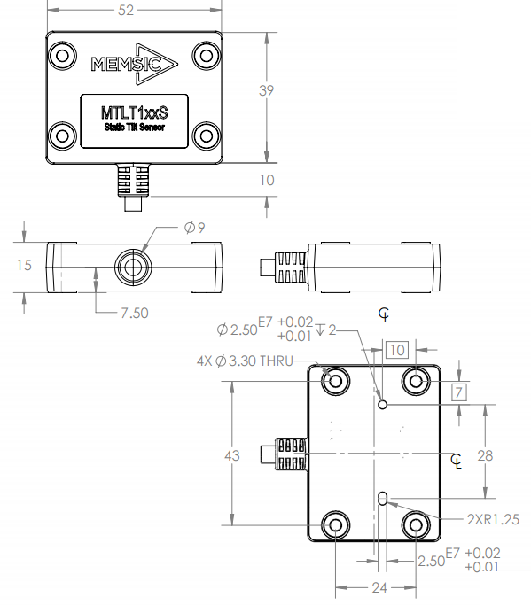
Appendix C. Sample Packet-Parser Code
Overview
This appendix includes sample code written in ANSI C for parsing packets from data sent by the MTLT1 Series Tilt Systems. This code can be used by a user application reading data directly from the MTLT1 Series product, or perhaps from a log file.
The sample code contains the actual parser, but also several support functions for CRC calculation and circular queue access.:
- process_memsic_packet – for parsing out packets from a queue. Returns these fields in structure ACEINNA_PACKET (see below). Checks for CRC errors
- calcCRC – for calculating CRC on packets.
- Initialize - initialize the queue
- AddQueue - add item in front of queue
- DeleteQueue - return an item from the queue
- peekWord - for retrieving 2-bytes from the queue, without popping
- peekByte – for retrieving a byte from the queue without popping
- Pop - discard item(s) from queue
- Size – returns number of items in queue
- Empty – return 1 if queue is empty, 0 if not
- Full - return 1 if full, 0 if not full
The parser will parse the queue looking for packets. Once a packet is found and the CRC checks out, the packet’s fields are placed in the ACEINNA_PACKET structure. The parser will then return to the caller. When no packets are found the parser will simply return to the caller with return value 0.
The ACEINNA_PACKET stucture is defined as follows:
typedef struct memsic_packet
{
unsigned short packet_type;
char length;
unsigned short crc;
char data[256];
} ACEINNA_PACKET;
Typically, the parser would be called within a loop in a separate process, or in some time triggered environment, reading the queue looking for packets. A separate process might add data to this queue when it arrives. It is up to the user to ensure circular-queue integrity by using some sort of mutual exclusion mechanism within the queue access functions.
Code listing
#include <stdio.h>
/* buffer size */
#define MAXQUEUE 500
/*
* circular queue
*/
typedef struct queue_tag
{
int count;
int front;
int rear;
char entry[MAXQUEUE];
} QUEUE_TYPE;
/*
* ACEINNA packet
*/
typedef struct memsic_packet
{
unsigned short packet_type;
char length;
unsigned short crc;
char data[256];
} ACEINNA_PACKET;
QUEUE_TYPE circ_buf;
/***************************************************************************
* FUNCTION: process_memsic_packet looks for packets in a queue
* ARGUMENTS: queue_ptr: is pointer to queue to process
* result: will contain the parsed info when return value is 1
* RETURNS: 0 when failed.
* 1 when successful
*******************************************************************************/
int process_memsic_packet(QUEUE_TYPE *queue_ptr, ACEINNA_PACKET *result)
{
unsigned short myCRC = 0, packetCRC = 0, packet_type = 0, numToPop=0, counter=0;
char packet[100], tempchar, dataLength;
if(Empty(queue_ptr))
{
return 0; /* empty buffer */
}
/* find header */
for(numToPop=0; numToPop+1<Size(queue_ptr) ;numToPop+=1)
{
if(0x5555==peekWord(queue_ptr, numToPop)) break;
}
Pop(queue_ptr, numToPop);
if(Size(queue_ptr) <= 0)
{
/* header was not found */
return 0;
}
/* make sure we can read through minimum length packet */
if(Size(queue_ptr)<7)
{
return 0;
}
/* get data length (5th byte of packet) */
dataLength = peekByte(queue_ptr, 4);
/* make sure we can read through entire packet */
if(Size(queue_ptr) < 7+dataLength)
{
return 0;
}
/* check CRC */
myCRC = calcCRC(queue_ptr, 2,dataLength+3);
packetCRC = peekWord(queue_ptr, dataLength+5);
if(myCRC != packetCRC)
{
/* bad CRC on packet – remove the bad packet from the queue and return */
Pop(queue_ptr, dataLength+7);
return 0;
}
/* fill out result of parsing in structure */
result->packet_type = peekWord(queue_ptr, 2);
result->length = peekByte(queue_ptr, 4);
result->crc = packetCRC;
for(counter=0; counter < result->length; counter++)
{
result->data[counter] = peekByte(queue_ptr, 5+counter);
}
Pop(queue_ptr, dataLength+7);
return 1;
}
/***************************************************************************
* FUNCTION: calcCRC calculates a 2-byte CRC on serial data using
* CRC-CCITT 16-bit standard maintained by the ITU
* (International Telecommunications Union).
* ARGUMENTS: queue_ptr is pointer to queue holding area to be CRCed
* startIndex is offset into buffer where to begin CRC calculation
* num is offset into buffer where to stop CRC calculation
* RETURNS: 2-byte CRC
*******************************************************************************/
unsigned short calcCRC(QUEUE_TYPE *queue_ptr, unsigned int startIndex, unsigned int num) {
unsigned int i=0, j=0;
unsigned short crc=0x1D0F; //non-augmented inital value equivalent to augmented initial value 0xFFFF
for (i=0; i<num; i+=1) {
crc ^= peekByte(queue_ptr, startIndex+i) << 8;
for(j=0;j<8;j+=1) {
if(crc & 0x8000) crc = (crc << 1) ^ 0x1021;
else crc = crc << 1;
}
}
return crc;
}
/***************************************************************************
* FUNCTION: Initialize - initialize the queue
* ARGUMENTS: queue_ptr is pointer to the queue
*******************************************************************************/
void Initialize(QUEUE_TYPE *queue_ptr)
{
queue_ptr->count = 0;
queue_ptr->front = 0;
queue_ptr->rear = -1;
}
/***************************************************************************
* FUNCTION: AddQueue - add item in front of queue
* ARGUMENTS: item holds item to be added to queue
* queue_ptr is pointer to the queue
* RETURNS: returns 0 if queue is full. 1 if successful
*******************************************************************************/
int AddQueue(char item, QUEUE_TYPE *queue_ptr)
{
int retval = 0;
if(queue_ptr->count >= MAXQUEUE)
{
retval = 0; /* queue is full */
}
else
{
queue_ptr->count++;
queue_ptr->rear = (queue_ptr->rear + 1) % MAXQUEUE;
queue_ptr->entry[queue_ptr->rear] = item;
retval = 1;
}
return retval;
}
/***************************************************************************
* FUNCTION: DeleteQeue - return an item from the queue
* ARGUMENTS: item will hold item popped from queue
* queue_ptr is pointer to the queue
* RETURNS: returns 0 if queue is empty. 1 if successful
*******************************************************************************/
int DeleteQueue(char *item, QUEUE_TYPE *queue_ptr)
{
int retval = 0;
if(queue_ptr->count <= 0)
{
retval = 0; /* queue is empty */
}
else
{
queue_ptr -> count–;
*item = queue_ptr->entry[queue_ptr->front];
queue_ptr->front = (queue_ptr->front+1) % MAXQUEUE;
retval=1;
}
return retval;
}
/***************************************************************************
* FUNCTION: peekByte returns 1 byte from buffer without popping
* ARGUMENTS: queue_ptr is pointer to the queue to return byte from
* index is offset into buffer to which byte to return
* RETURNS: 1 byte
* REMARKS: does not do boundary checking. please do this first
*******************************************************************************/
char peekByte(QUEUE_TYPE *queue_ptr, unsigned int index) {
char byte;
int firstIndex;
firstIndex = (queue_ptr->front + index) % MAXQUEUE;
byte = queue_ptr->entry[firstIndex];
return byte;
}
/***************************************************************************
* FUNCTION: peekWord returns 2-byte word from buffer without popping
* ARGUMENTS: queue_ptr is pointer to the queue to return word from
* index is offset into buffer to which word to return
* RETURNS: 2-byte word
* REMARKS: does not do boundary checking. please do this first
*******************************************************************************/
unsigned short peekWord(QUEUE_TYPE *queue_ptr, unsigned int index) {
unsigned short word, firstIndex, secondIndex;
firstIndex = (queue_ptr->front + index) % MAXQUEUE;
secondIndex = (queue_ptr->front + index + 1) % MAXQUEUE;
word = (queue_ptr->entry[firstIndex] << 8) & 0xFF00;
word |= (0x00FF & queue_ptr->entry[secondIndex]);
return word;
}
/***************************************************************************
* FUNCTION: Pop - discard item(s) from queue
* ARGUMENTS: queue_ptr is pointer to the queue
* numToPop is number of items to discard
* RETURNS: return the number of items discarded
*******************************************************************************/
int Pop(QUEUE_TYPE *queue_ptr, int numToPop)
{
int i=0;
char tempchar;
for(i=0; i<numToPop; i++)
{
if(!DeleteQueue(&tempchar, queue_ptr))
{
break;
}
}
return i;
}
/***************************************************************************
* FUNCTION: Size
* ARGUMENTS: queue_ptr is pointer to the queue
* RETURNS: return the number of items in the queue
*******************************************************************************/
int Size(QUEUE_TYPE *queue_ptr)
{
return queue_ptr->count;
}
/***************************************************************************
* FUNCTION: Empty
* ARGUMENTS: queue_ptr is pointer to the queue
* RETURNS: return 1 if empty, 0 if not
*******************************************************************************/
int Empty(QUEUE_TYPE *queue_ptr)
{
return queue_ptr->count <= 0;
}
/***************************************************************************
* FUNCTION: Full
* ARGUMENTS: queue_ptr is pointer to the queue
* RETURNS: return 1 if full, 0 if not full
*******************************************************************************/
int Full(QUEUE_TYPE *queue_ptr)
{
return queue_ptr->count >= MAXQUEUE;
}
Appendix D. Sample Packet Decoding
- Example payload from Angle Data Packet 2 (A2)
- Example payload from Scaled Data Packet 1 (S1)
Warranty and Support Information
Customer Service
As a Aceinna customer you have access to product support services, which include:
- Single-point return service
- Web-based support service
- Same day troubleshooting assistance
- Worldwide Aceinna representation
- Onsite and factory training available
- Preventative maintenance and repair programs
- Installation assistance available
Contact Directory
United States: Phone: 1-408-964-9700 (8 AM to 5 PM PST)
Fax: 1-408-854-7702 (24 hours)
Email: techsupportca@memsic.com
Non-U.S.: Refer to website www.memsic.com
Return Procedure
Authorization
Before returning any equipment, please contact Aceinna to obtain a Returned Material Authorization number (RMA).
Be ready to provide the following information when requesting a RMA:
- Name
- Address
- Telephone, Fax, Email
- Equipment Model Number
- Equipment Serial Number
- Installation Date
- Failure Date
- Fault Description
- Will it connect to NAV-VIEW?
Identification and Protection
If the equipment is to be shipped to Aceinna for service or repair, please attach a tag TO THE EQUIPMENT, as well as the shipping container(s), identifying the owner. Also indicate the service or repair required, the problems encountered and other information considered valuable to the service facility such as the list of information provided to request the RMA number.
Place the equipment in the original shipping container(s), making sure there is adequate packing around all sides of the equipment. If the original shipping containers were discarded, use heavy boxes with adequate padding and protection.
Sealing the Container
Seal the shipping container(s) with heavy tape or metal bands strong enough to handle the weight of the equipment and the container.
Marking
Please write the words, “*FRAGILE, DELICATE INSTRUMENT*” in several places on the outside of the shipping container(s). In all correspondence, please refer to the equipment by the model number, the serial number, and the RMA number.
Return Shipping Address
Use the following address for all returned products:
Aceinna, Inc.
3180 De La Cruz Blvd, #130
Santa Clara, CA 95054
Attn: RMA Number (XXXXXX)